
General
KYN61-40.5 type metal-claded withdrawable type AC metal-enclosed switchgear (hereinafter referred to as "switchgear") is mainly characterized by the use of ZN85-40.5 fully insulated vacuum circuit breakers and spring operating mechanisms in the cabinet, and the cabinet body is assembled by plastic coated steel, which improves the matching precision of the VCB and the cabinet. The VCB is easy to push and pull out and has strong interchangeability with beautiful appearance, complete solutions, safe and reliable use.
This product is used in 35kV three-phase AC 50Hz power system. It is used for receiving and distributing electric energy in power plants, substations and power distribution rooms of industrial and mining enterprises. It has control, protection and monitoring functions. This product complies with standards: GB3906 "Alternating-current metal-enclosed switchgear and controlgear for rated voltage above 3.6kV and up to and including 40.5kV", GB/T11022 "Common specifications for high-voltage switchgear and controlgear standards", DL/T404 "Alternating-current metal-enclosed switchgear and controlgear for rated voltages above 3.6kV and up to and including 40.5kV", IEC60298 "A.C. metal-enclosed switchgear and controlgear for rated voltages above 1 kV and up to and including 52kV".
Normal Use Conditions
● Ambient air temperature: -15℃~+40℃.
● Humidity conditions:
Daily average relative humidity: ≤95%, daily average water vapor pressure ≤2.2kPa.
The monthly average relative humidity is 90%, and the monthly average water vapor pressure is 1.8kPa.
● Altitude: ≤4000m.
● Earthquake intensity: ≤8 degrees.
● The surrounding air should not be contaminated by corrosive or combustible gas, water vapor, etc.
● Places without frequent severe vibration.
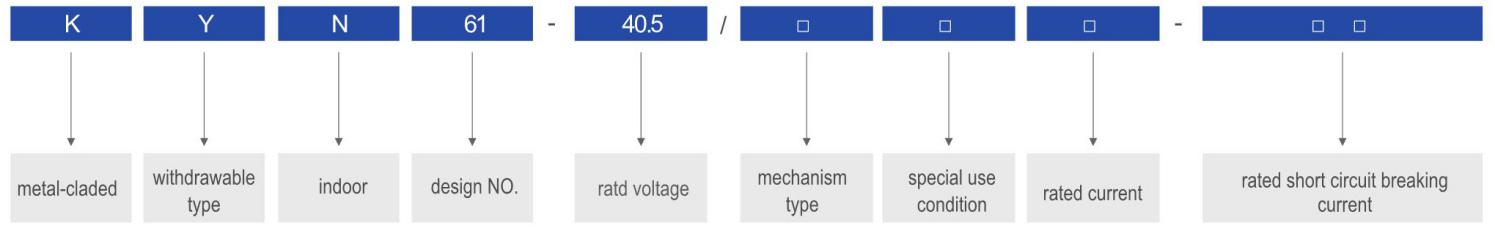
Type Description
Main Technical Parameters
| Item | Unit | Value | |
| Rated voltage | kV | 40.5 | |
| Rated current | Rated current of main bus | A | 630, 1250, 1600 |
| Rated current of equipped circuit breaker | A | 630, 1250, 1600 | |
| Insulation level | 1min power frequency withstand voltage:phase-to-phase, phase-to-earth/across open contacts | kV | 95/110 |
| Lightning impulse withstand voltage (peak):phase-to-phase, phase-to-earth,/across open contacts | kV | 185/215 | |
| Power frequency withstand voltage of auxiliary circuit and control circuit | V/1 min | 2000 | |
| Rated frequency | Hz | 50 | |
| Rated short circuit breaking current | kA | 20, 25, 31.5 | |
| Rated short time withstand current/rated short circuit duration | kA/4s | 20, 25, 31.5 | |
| Rated peak withstand current | kA | 50, 63, 80 | |
| Rated short circuit making current | kA | 50, 63, 80 | |
| Rated voltage of control circuit | IN | DC110/220, AC110/220 | |
| Protection degree | Switchgear enclosure | IP4X | |
| Compartment (when the doors are opened) | IP2X | ||
Main Technical Parameters
Technical Parameters of ZN85-40.5 Type Circuit Breaker with Spring Operating Mechanism(Integrated)
| Item | Unit | Value | |
| Rated voltage | kV | 40.5 | |
| Rated current | A | 630, 1250, 1600 | |
| Insulation level | 1min power frequency withstand voltage:phase-to-phase, phase-to-earth/across open contacts | kV | 95/110 |
| Lightning impulse withstand voltage (peak):phase-to-phase, phase-to-earth,/across open contacts | kV | 185/215 | |
| Power frequency withstand voltage of auxiliary circuit and control circuit | V/1 min | 2000 | |
| Rated frequency | Hz | 50 | |
| Rated short circuit breaking current | kA | 20, 25, 31.5 | |
| Rated short circuit making current | kA | 50, 63, 80 | |
| Rated peak withstand current | kA | 50, 63, 80 | |
| Rated short time withstand current/rated short circuit duration | kA/4s | 20, 25, 31.5 | |
| Mechanical life | times | 1000 | |
| Closing time | ms | 50~100 | |
| Opening time | ms | 35~60 | |
| Rated operating sequence | O-0.3s-CO-180s-CO | ||
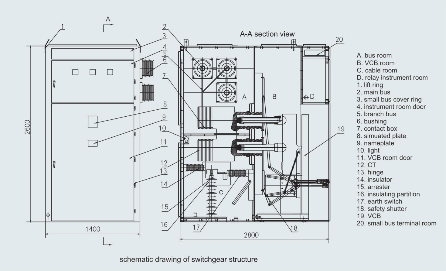
Structure
This product is divided into two parts: cabinet and VCB. The cabinet is made of bent steel plate and assembled with bolts after spraying. According to functional characteristics, it can be divided into four parts: small bus room, relay instrument room, VCB room, cable room and bus room, each part is separated by a grounded metal partition. The protection degree of the switchgear enclosure is IP4X; when the VCB room door is opened, the protection degree is IP2X.
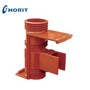
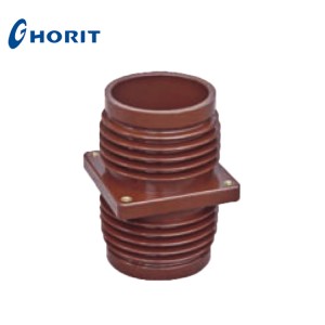
The switchgear has main circuit schemes such as cable inlet and outlet, overhead inlet and outlet, bus connection, disconnection, voltage transformer, and lightning arrester. The busbar adopts composite insulation, and the inter-phase and connectors are equipped with insulating sleeves made of flame-retardant materials. The adjacent cabinets of the main busbar are separated by busbar sleeves, which can effectively prevent the accident from spreading and play an auxiliary support role for the main busbar. The cable room is equipped with earth switch, overvoltage protection device, etc.
There is a metal safety shutter in front of the contact box. The upper and lower safety shutter are automatically opened when the VCB moves from the disconnecting/test position to the working position, and automatically closed when the VCB moves in the opposite direction, effectively disconnecting from the high voltage. The interlocking between the main switch, VCB, earth switch and cabinet door adopts mandatory mechanical interlocking method to meet the "five prevention" functional requirements.
The circuit breaker adopts a screw rod drive propulsion mechanism and an overrunning clutch. The screw rod nut feed mechanism can be easily operated to move the VCB between the test position and the working position. With the help of the self-locking property of the screw rod nut, the VCB can be reliably locked in the working position to prevent the VCB from accident caused by fleeing due to electric power. The overrunning clutch works when the VCB moves back to the test position and when it reaches the working position. It makes the operating shaft and the screw shaft automatically disengage and idle, which can prevent misoperation and damage the feed mechanism. Other VCBs use lever feed mechanism. The test work position is locked by positioning pins.
The overall dimensions of the cabinet are: W×D ×H (mm): 1400×2800×2600
Main Circuit Scheme Diagrams
| Primary scheme NO. | 1 | 2 | 3 | 4 | 5 | |
| Main circuit scheme diagram | 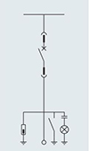 | 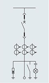 | 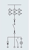 | 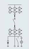 | 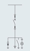 | |
| Main circuit components | Vacuum circuit breaker ZN85-40.5 | 1 | 1 | 1 | 1 | 1 |
| Current transformer LZZBJ9-35 | 1-3 | 1-3 | 4-6 | |||
| Voltage transformer JDZ9-35 | ||||||
| Arrester HY5WZ2 | 0 or 3 optional | |||||
| Earth switch JN24-40.5 | 0-1 optional | |||||
| Charged display | 0-1 optional | |||||
| Fuse XRNP-35 | ||||||
| Power transformer SC9-35 | ||||||
| Application | Overhead inlet (outlet) | |||||