
Application
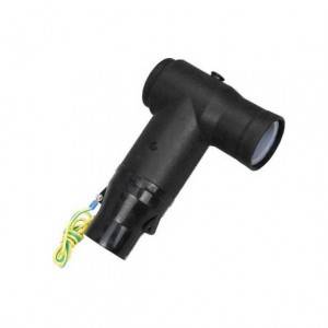
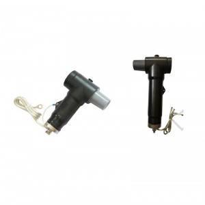
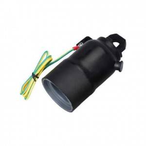
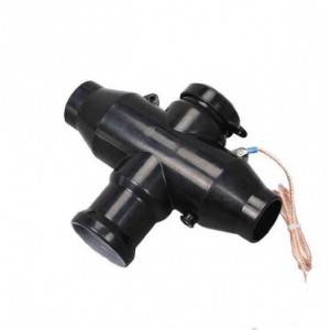
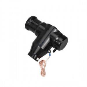
* The 630A European rear connector can be connected to the European front joint or another rear connector to provide an extended cable connection circuit (branch). It cannot be directly connected to the bushing seat and the wall bushing: its end can be directly blocked with an insulating plug. It can also be extended to connect another European-style rear connector or rear-arrester.
* Suitable for indoor and outdoor installation.
* Rated voltage: 8.7/15kV, 18/24kV
* Continuous rated current 630A; (900A overload can last for 8 hours)
* Extendable (JBK) rear connector or (HBLQ) series surge arrester to achieve multi-channel installation or provide overvoltage protection.
* Cable characteristics:
-Copper or aluminum conductor
-Has semi-conductive or metal shield
-Cable conductor cross section: 12kV 25-500mm2, 24kV 25-500mm2
Type Description

Feature
* When mated with a suitable European style detachable front joint or European style detachable rear connector, it provides a fully shielded and fully sealed detachable connection;
* Can be operated under water and other harsh conditions for a long time;
* The built-in capacitance test point is used to determine the charged state of the circuit, and must be used in conjunction with the charged display;
* No requirements for minimum safety distance between phases;
* The installation can be vertical, horizontal or any angle
Structure
1. Double-headed bolts: Metal bolts ensure that the conductor and the bushing are tightly matched.
2. Insulation layer: unique formula and mixing technology ensure the high quality of prefabricated insulating silicone rubber.
3. Insulator: The epoxy resin insulator contains threaded metal parts to ensure a close fit with the stud bolts.
4. Inner semiconducting layer: Prefabricated conductive silicone rubber effectively controls electrical stress.
5. Stress cone: Stress cones of different sizes are used with cable joints to ensure water sealing and cable stress relief.
6. Grounding eye: pre-injected into the outer shield for the connection of the grounding wire.
7. Outer semiconducting layer: The prefabricated conductive rubber overlaps with the cable shielding layer to make the shielding continuous and ensure that the outer semiconducting layer is grounded.
8. Crimping terminal: All-copper or copper-aluminum crimping terminal is suitable for copper or aluminum conductor.

Installation
* No special tools, straps or padding required;
* The cable connector is energized and operated immediately after being installed to the relevant parts;
* Provide regular assembly parts and installation manual.
* (Please contact our company for special requirements)
| European style front joint body | utilityknife |
| stress cone | band Aid |
| insulator | cleaning paper |
| dust cap | silicone grease |
| crimp terminal (copper or copper aluminum) | gloves (white, yellow) |
| gloves (disposable) | |
| socket wrench | sealant (red) |
| M16/12 double-head screw | nylon cable tie (buckle) |
| M12 nut, flat washer, spring washer | PVC electrical tape (red yellow, green) |
| tape | certificate of quality |
| sandpaper | installation instruction manual |
Standard Packaging
12KV Cable Type Configuration Table
| Product model | Conductor cross section (mm2) | Cable insulation outer diameter (mm) | Cable type | Corresponding code |
| JBK-12/630-25 | 25 | 16.6 | 8.7/15 | O |
| JBK-12/630-35 | 35 | 17.6 | 8.7/15 | A |
| JBK-12/630-50 | 50 | 19 | 8.7/15 | A |
| JBK-12/6 30-70 | 70 | 20.6 | 8.7/15 | A |
| JBK-12/630-95 | 95 | 22.2 | 8.7/15 | B |
| JBK-12/630-120 | 120 | 23.6 | 8.7/15 | B |
| JBK-12/630-150 | 150 | 25.5 | 8.7/15 | C |
| JBK-12/630-185 | 185 | 26.7 | 8.7/15 | C |
| JBK-12/630-240 | 240 | 29 | 8.7/15 | D |
| JBK-12/630-300 | 300 | 31.2 | 8.7/15 | D |
| JBK-12/630-400 | 400 | 34.4 | 8.7/15 | AND |
| JBK-12/630-500 | 500 | 37.2 | 8.7/15 | F |
24KV Cable Type Configuration Table
| Product model | Conductor cross section (mm2) | Cable insulation outer diameter (mm) | Cable type | Corresponding code |
| JBK-24/630-25 | 25 | 16.6 | 8.7/15 | O |
| JBK-24/630-35 | 35 | 17.6 | 8.7/15 | A |
| JBK-24/630-50 | 50 | 19 | 8.7/15 | A |
| JBK-24/630-70 | 70 | 20.6 | 8.7/15 | A |
| JBK-24/630-95 | 95 | 22.2 | 8.7/15 | B |
| JBK-24/630-120 | 120 | 23.6 | 8.7/15 | B |
| JBK-24/630-150 | 150 | 25.2 | 8.7/15 | C |
| JBK-24/630-185 | 185 | 26.7 | 8.7/15 | C |
| JBK-24/630-240 | 240 | 29 | 8.7/15 | D |
| JBK-24/630-300 | 300 | 31.2 | 8.7/15 | D |
| JBK-24/630-400 | 400 | 34.4 | 8.7/15 | AND |
| JBK-24/630-500 | 500 | 37.2 | 8.7/15 | F |